
How does auto calibration function on the Fisher DVC6200 digital valve controller, and what triggers calibration failure during site commissioning? The Fisher FIELDVUE DVC6200 relies on auto calibration to match device parameters with real-world valve mechanical travel. New installations require this calibration before normal operation. Field technicians meet frequent failed calibration events during commissioning. This article covers internal calibration logic, field operation workflow, failure root causes and special zero-point calibration for device swap, to support fast on-site diagnostics.
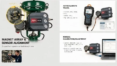
How Does DVC6200 Auto Calibration Work
Auto-calibration runs fully automatic after trigger, yet three core internal tasks execute in sequence.
1. End-point search
The controller drives valve full stroke to locate physical high-travel and low-travel endpoints. It records actual 0% and 100% valve travel positions instead of theoretical configured values.
2. Minor Loop Feedback (MLFB) sensor calibration
The unit measures relay beam swing range at both travel ends. It sets correct sensitivity parameters for the MLFB feedback sensor.
3. Output bias calibration
The controller calculates and writes matched output bias values, to guarantee consistent positioning response across full valve travel range.
The whole workflow depends on free full-stroke movement of valve and actuator assembly. Any restriction to valve travel breaks auto-calibration execution.
Step-by-Step Procedure for DVC6200 Auto Calibration
Prepare compatible tools: HART communicator (375 / 475 / AMS Trex), or ValveLink software. Confirm instrument air supply and 4-20mA control loop ready before start.
Apply 4 mA analog input signal to DVC6200, power on HART communicator or ValveLink software.
Navigate menu path: Setting > Advanced Setup > Mode and Protection > Instrument Mode. Switch instrument to Out of Service mode to unlock calibration access.
Open Calibration menu and launch auto-travel calibration routine.
Follow on-screen prompts to adjust mA input values. For 50% prompt, set input signal to 12 mA. Complete all prompted signal adjustments.
Hold process until the Calibration menu page returns. This screen return confirms auto-calibration sequence finishes.
Switch instrument mode back to In Service as prompt displays.
Run manual full-stroke test for the valve. Verify valve opening and closing follows 4-20 mA input signal with linear response. This validation step confirms real-world valve performance instead of menu-only completion status.
What Causes DVC6200 Auto Calibration Failure
Auto-calibration stops or aborts from multiple field issues. Most faults come from mechanical installation, wiring or configuration error rather than controller hardware damage. Check items below when calibration fails.
1. Analog input signal too low
The DVC6200 requires analog input signal above 3.8 mA to run calibration. Current source or DCS output below this threshold terminates calibration. Adjust loop signal to minimum 4.0 mA then restart calibration.
2. Calibration timed-out
Timeout occurs when valve cannot reach travel endpoints within predefined time window. Common trigger: low tuning response setting slows valve actuator movement. Troubleshooting: Open Hot Key menu, select Stabilize/Optimize, choose Increase Response for faster tuning set. Rerun calibration after parameter update.
3. Low instrument supply pressure
Insufficient instrument air supply pressure prevents actuator from completing full stroke movement. Calibration routine cannot capture both endpoints and marks procedure as failed. Confirm air supply meets actuator specification before retry.
4. Wrong actuator size or spring range configuration
Mismatched actuator setup parameters cause abnormal calibration behavior or complete failure. Verify configuration matches hardware: spring-diaphragm actuator, single-acting piston, double-acting piston with or without spring. Update setup tool parameters to match physical actuator assembly.
5. Mechanical blockage or excessive valve friction
Auto-calibration needs unobstructed valve full stroke. Mechanical jamming, binding parts or high packing friction block physical travel. The controller cannot complete endpoint search. Inspect valve body, packing and actuator linkage for stuck components.
6. Incorrect feedback array installation
Mis-mounted travel feedback linkage or magnetic array stops accurate valve-position sensing. Check Hall sensor located on DVC6200 housing rear side. The Hall sensor must stay inside valid magnet travel range across full valve stroke. Use no less than 60% of magnet assembly travel span for position measurement. Limited magnet range reduces calibration accuracy even when calibration finishes without error alert.
7. Mismatched relay configuration and wiring
Physical relay hardware must match relay parameter entered inside setup tool. For single-acting direct configuration: route actuator pressure connection to Output A. For single-acting reverse setup with Relay B: route actuator pressure connection to Output B. Mismatch between configured relay model and field wiring generates wrong calibration result or procedure failure.
8. Travel sensor runs out of valid range
Travel sensor exceeds magnet array valid span during valve stroke. The issue arises from wrong initial mounting or actuator travel larger than sensor calibrated span. Position feedback data becomes invalid for calibration sequence. Re-align feedback magnet assembly and confirm stroke coverage.
Special Case: Zero-Point Calibration for DVC6200 Instrument Replacement
Zero-point calibration serves for DVC6200-to-DVC6200 swap, when plant cannot shut down process and full-stroke auto-calibration is not allowed. Strict prerequisites must satisfy before operation.
The original magnetic feedback array keeps unchanged and stays at original mounting position. No relocation after prior calibration.
Lock valve mechanically to fixed position with handwheel or equivalent hardware. Do not start zero-point calibration if safe valve locking cannot complete. Unexpected valve movement creates personal injury and equipment damage risk.
This procedure only applies to replacement between two DVC6200 units. Zero-point calibration does not support cross-model swap such as DVC6000 upgrade to DVC6200.
Note: Zero-point calibration is not a replacement for standard full-stroke auto-calibration. Perform complete auto-calibration when process shutdown becomes available.
Conclusion
Fisher FIELDVUE DVC6200 auto-calibration delivers automated valve stroke parameter setup, yet calibration success depends on pre-conditions: correct actuator configuration, properly installed magnetic feedback array, qualified instrument air supply and mechanically free valve full-stroke travel. Most calibration failures trace back to these pre-condition items. Systematically go through the checklist instead of repeated blind retries, to reduce field troubleshooting time. Reach our technical team for persistent DVC6200 calibration faults and fleet-wide calibration standard support.